How To Solder Instrument Cables: 11 Steps To Make Your Own Jack Cable!
Pro Tips for Better Sound and Lower Costs
 4,4 / 5,0 |
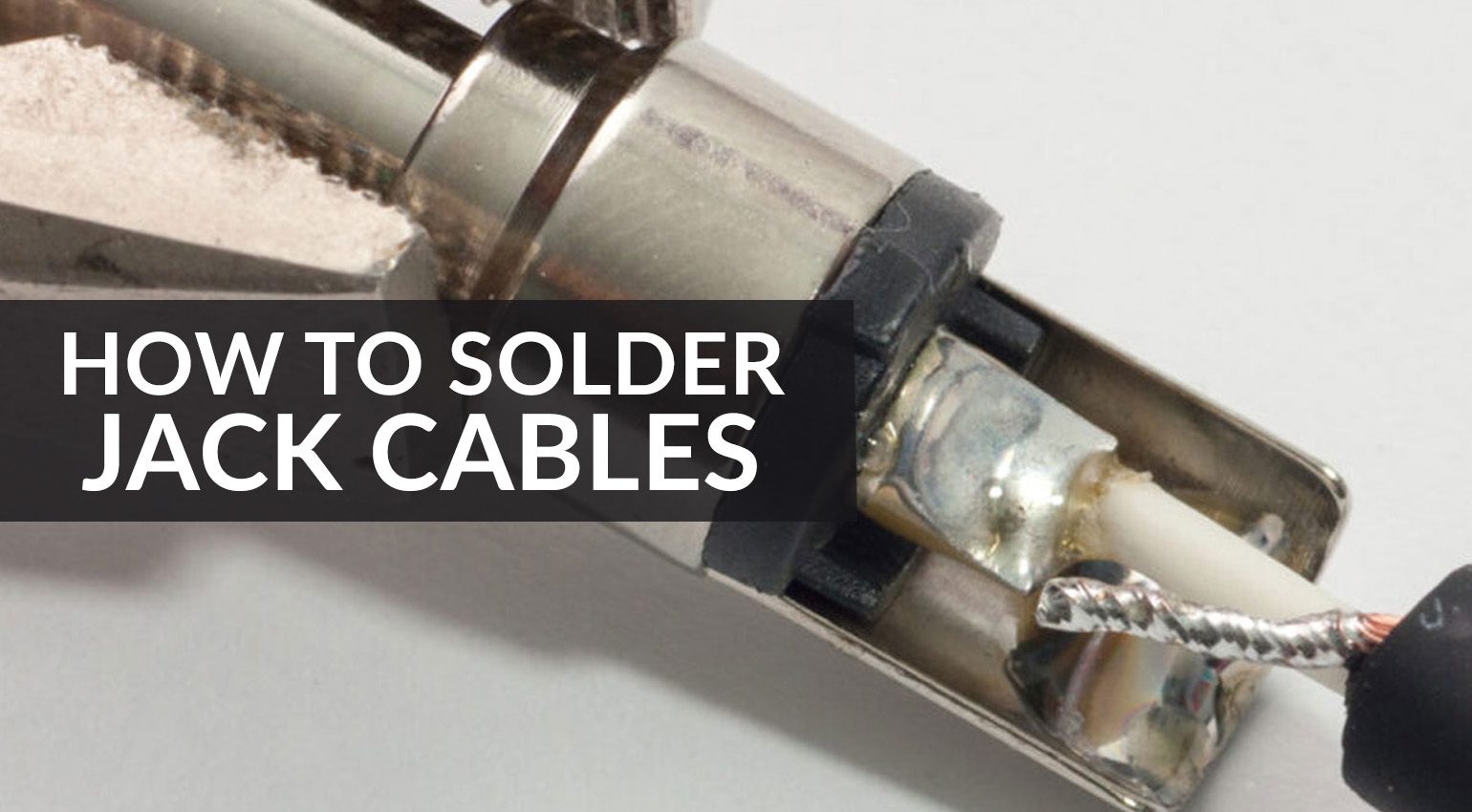

Soldering instrument cables yourself isn’t difficult at all! If you know how to solder, you can save a pretty penny by making and/or repairing your own cables. And it’s fun and rewarding! Here’s how to solder instrument cables in 11 simple steps.
How To Solder Instrument Cables
Ready-made cables are available everywhere, so why should you bother to pick up a soldering iron? Well, it happened again just the other day: Halfway through soundcheck, a cable for the guitarist’s channel switch was destroyed in a small accident.
Long faces and discussions ensued, but then the sound engineer showed up and said: “Let me take care of that, I’ve got a soldering iron!” A few minutes later, the torn-off jack plug was back on, the band was happy, and the show was saved.
Learning to solder your own instrument cables is absolutely worth it, not just for quick repairs. Besides saving a few bucks, assembling your cables yourself means that you can configure them to the exact lengths and connector combinations you need. Plus, soldering is not rocket science – in fact, it’s quite easy. It’s like riding a bicycle: Once you get the hang of it, you’ll never unlearn it.
But doesn’t soldering cables require expensive equipment? Not necessarily: The cable mentioned earlier was repaired with a cheap soldering iron from a hardware store, some electronic solder from the depths of the toolbox, and a pair of pliers!
What Do I Need to Solder Instrument Cables Myself?
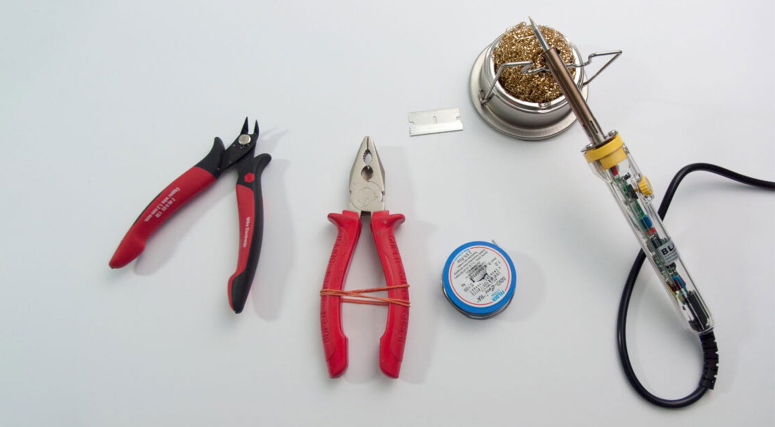
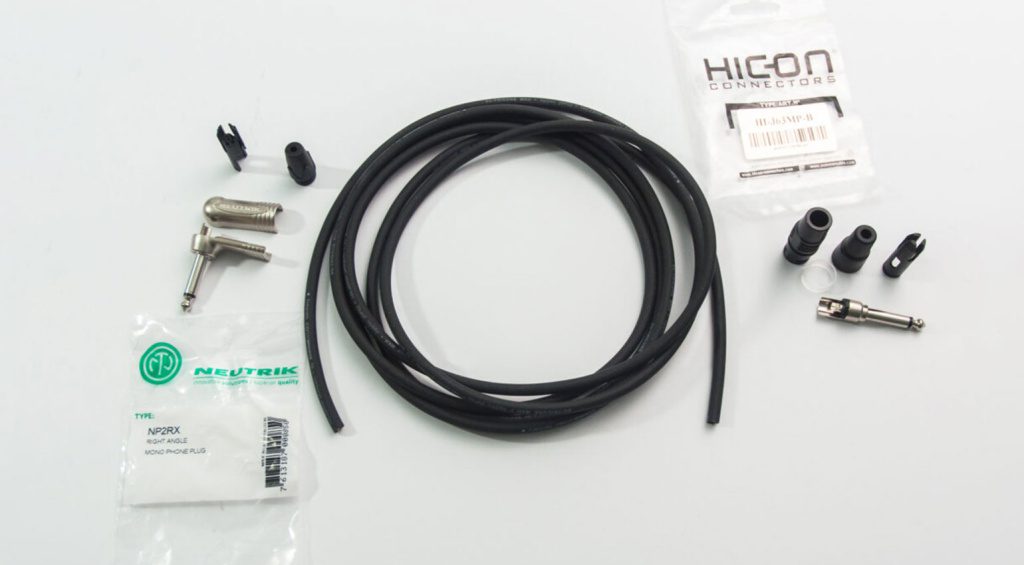
Besides the cables and plugs, this is the minimum equipment you need to solder your own instrument cables:
- soldering iron
- solder
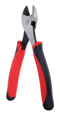
- side cutters
- all-purpose scissors
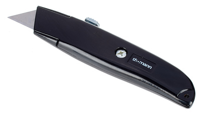
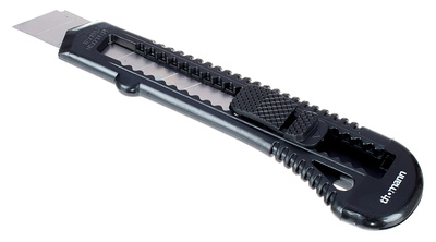
- box cutter or razor blade
- rubber band
- safety glasses


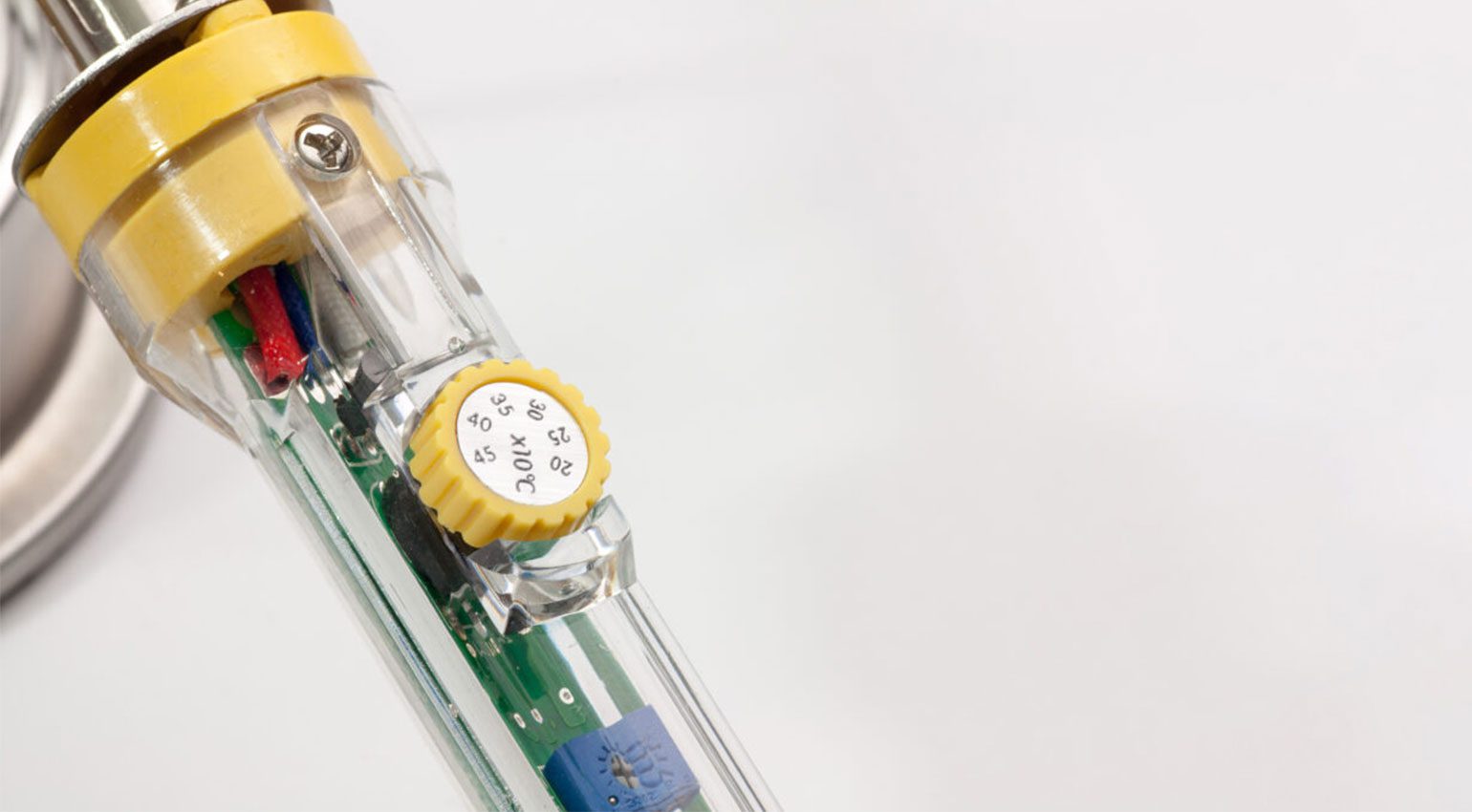
The good news is that you don’t need any expensive special tools for soldering jack cables. Quite the opposite: I’d like to show you that you can absolutely get by with simple and inexpensive tools. That’s why I decided not to use my professional soldering station for this tutorial. Instead, I ordered a cheap handheld soldering iron just like the one the sound engineer had in his toolbox.
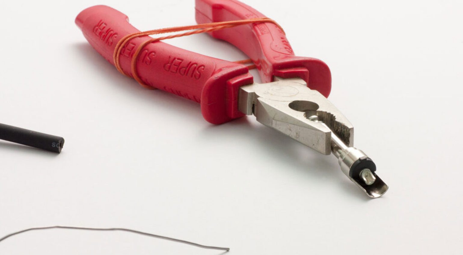
I use standard Sn60Pb40 electronic solder with a diameter of 1 mm. This type of solder contains lead, which has one main advantage over the (healthier) lead-free solder that’s now standard in professional manufacturing: it is much easier to work with, especially for amateurs. Since you’re not going to be soldering 24/7, I believe it’s acceptable to use leaded solder. Plus, you can easily tell by the appearance of the solder joint if you’ve done everything right. An old razor blade or utility knife, side / diagonal cutters, combination pliers, and a rubber band complete your basic toolkit. In fact, you could even get by without the side cutters, although my ancient combination pliers are no longer sharp enough to cut a cable.
Unbalanced Instrument Cables and Jack Connectors
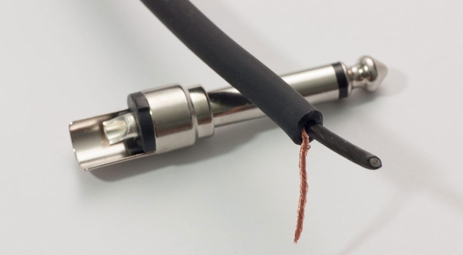
The basic instrument or guitar cable is a perfect starting point for learning how to solder. This type of cable is “unbalanced”, which means that it has only two separate conductors: the signal-carrying “hot” inner conductor and the shield that encloses the inner conductor and protects the signal from interference. That’s two solder joints per connector, so it’s a very manageable project.
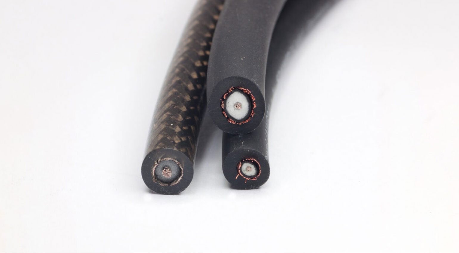
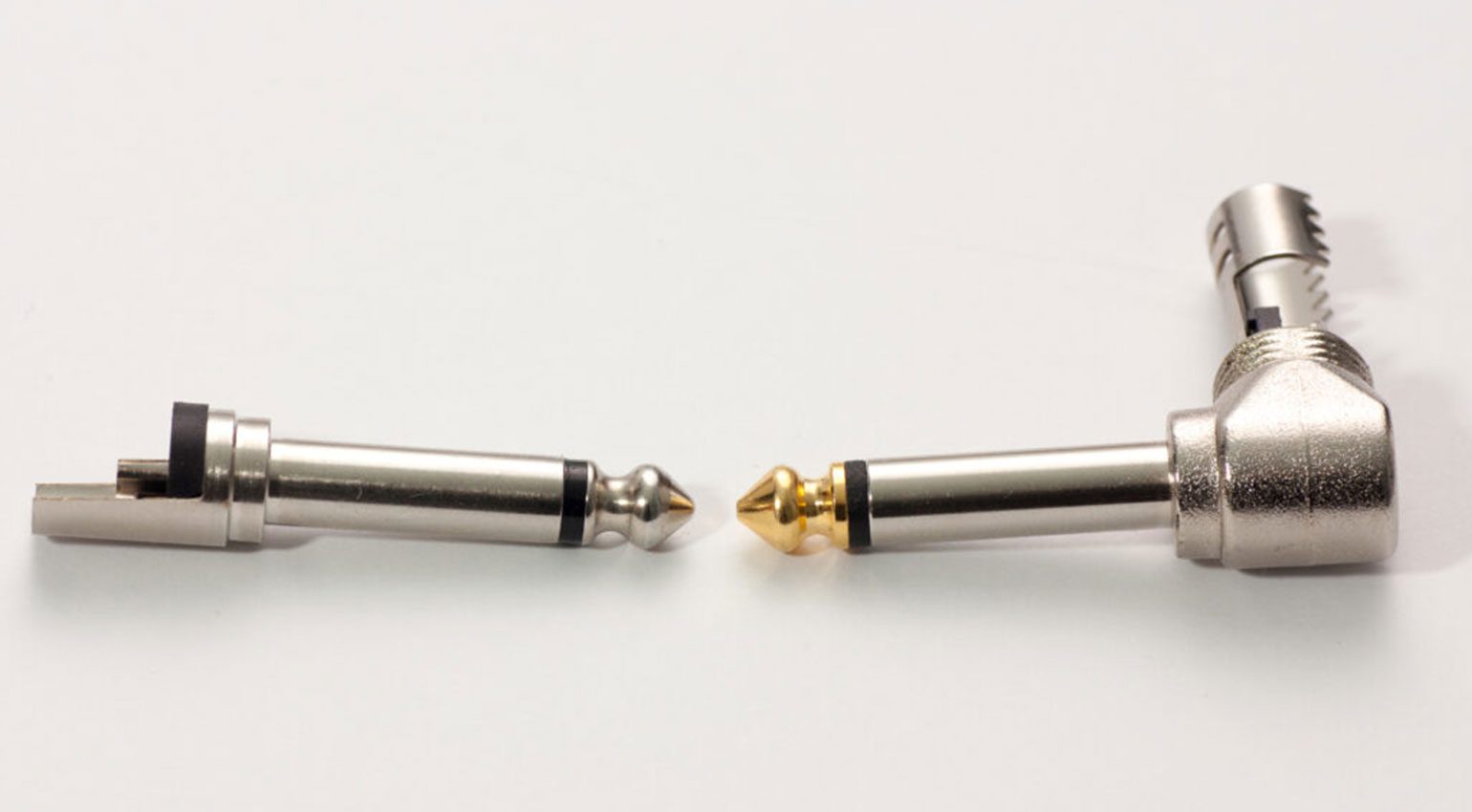
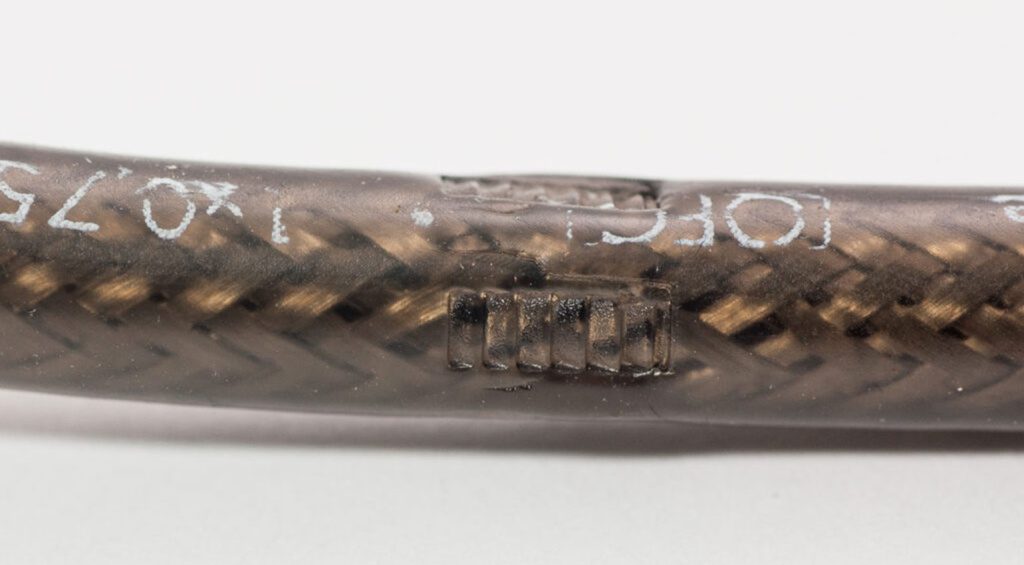
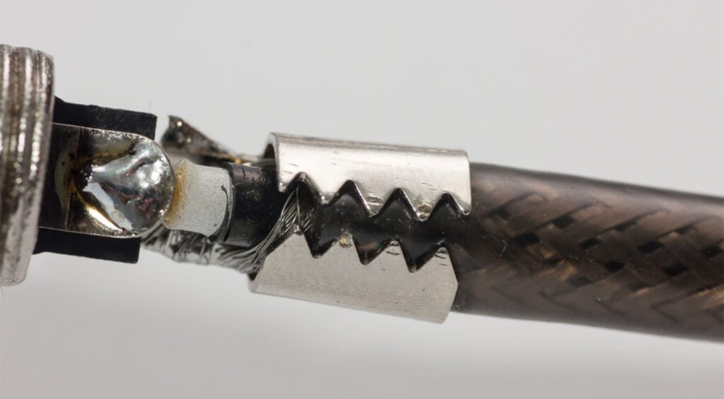
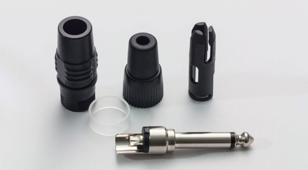
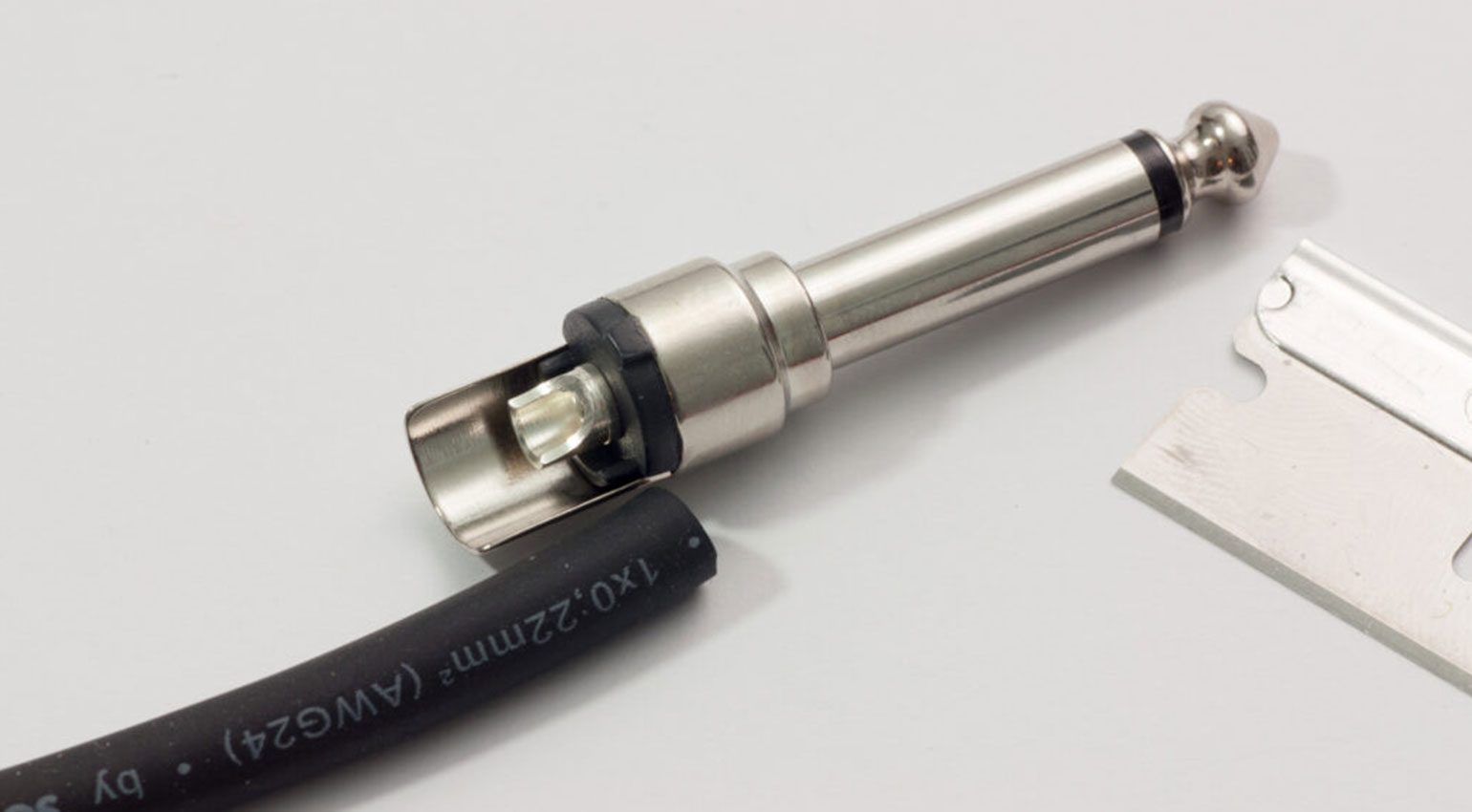
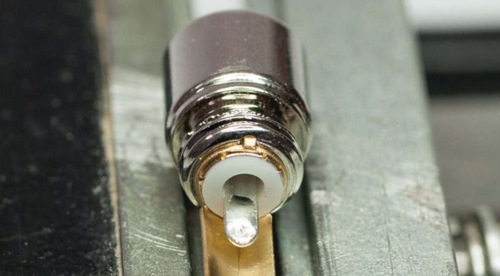
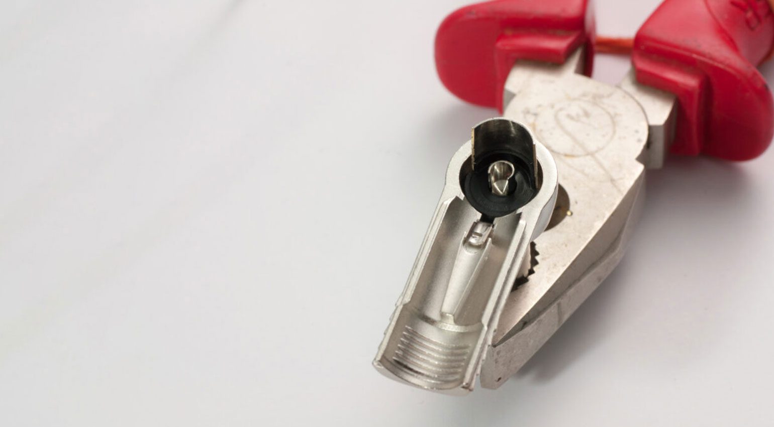
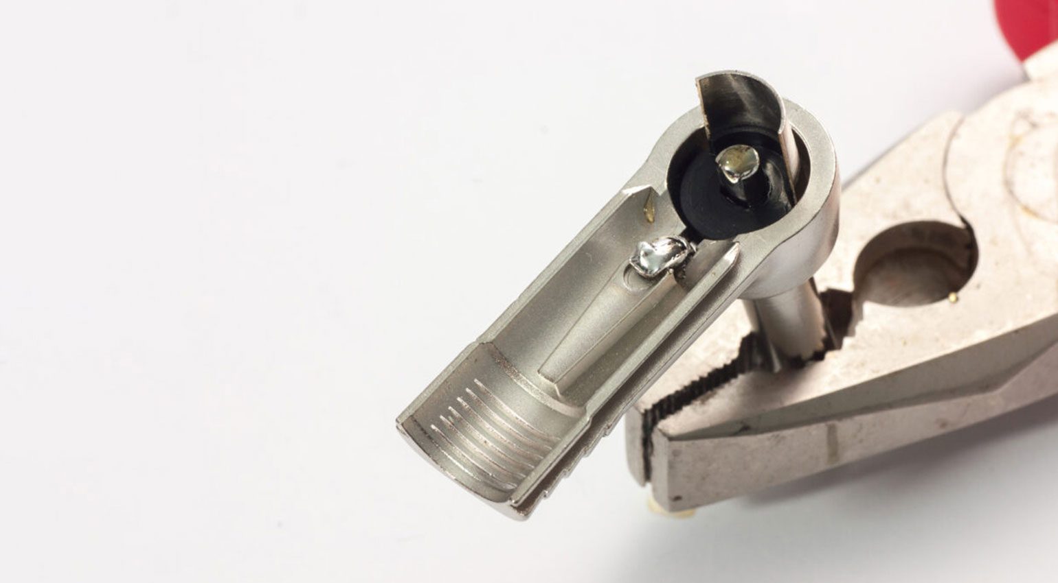
Jack connectors for unbalanced instrument cables come in many different variants: Straight, angled, with thick or thin housings and with gold or nickel-plated connectors. While they differ in construction, they’re identical in function: there is a shaft, also called a “sleeve”, with a diameter of 1/4” / 6.35 mm, which is connected to the shield of the cable. The tip of the plug is insulated from the shaft by a black plastic disc. This tip is connected to the “hot” inner conductor of the cable. This type of unbalanced/mono jack plug is also known as “TS” (tip-sleeve).
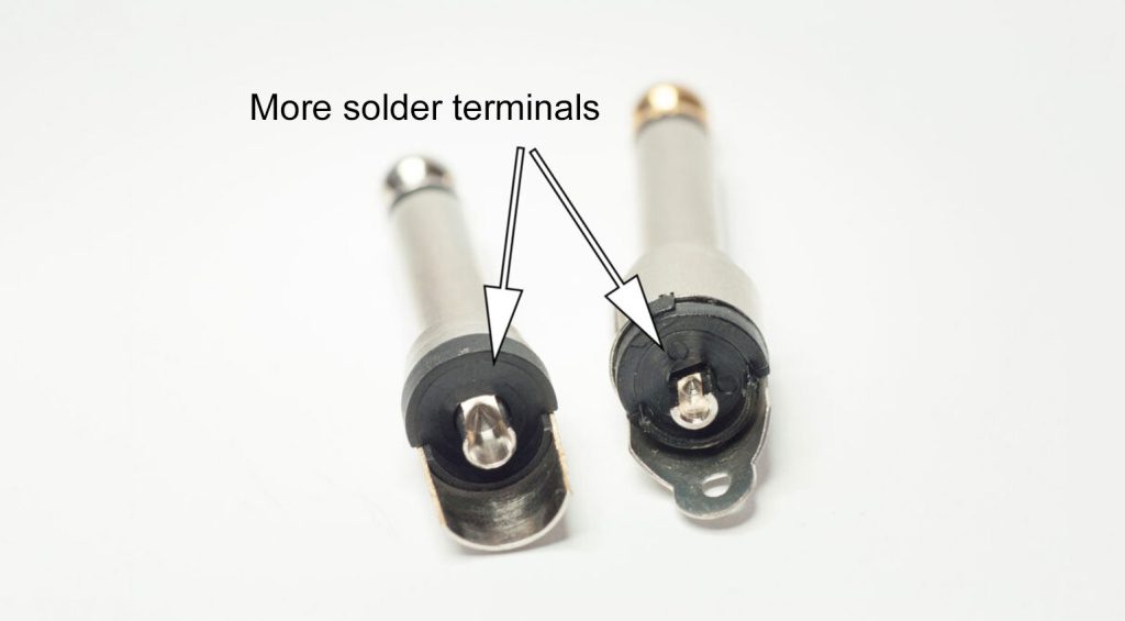
For soldering the cable to the plug, each plug has soldering terminals for the tip and the sleeve. These come in many shapes: some look like little cups, others are lugs with a hole in them. If you are unsure which terminal is connected to the tip or sleeve, you can use a multimeter or continuity tester to find out.

Strain Relief
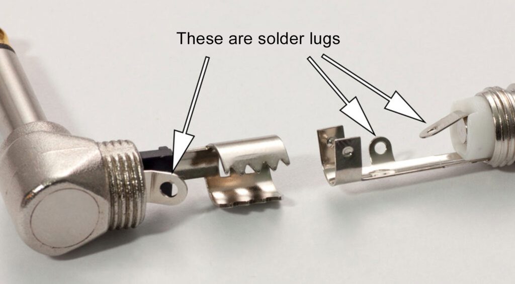
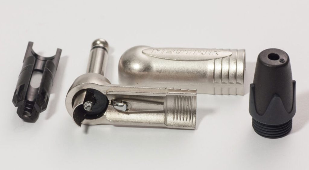
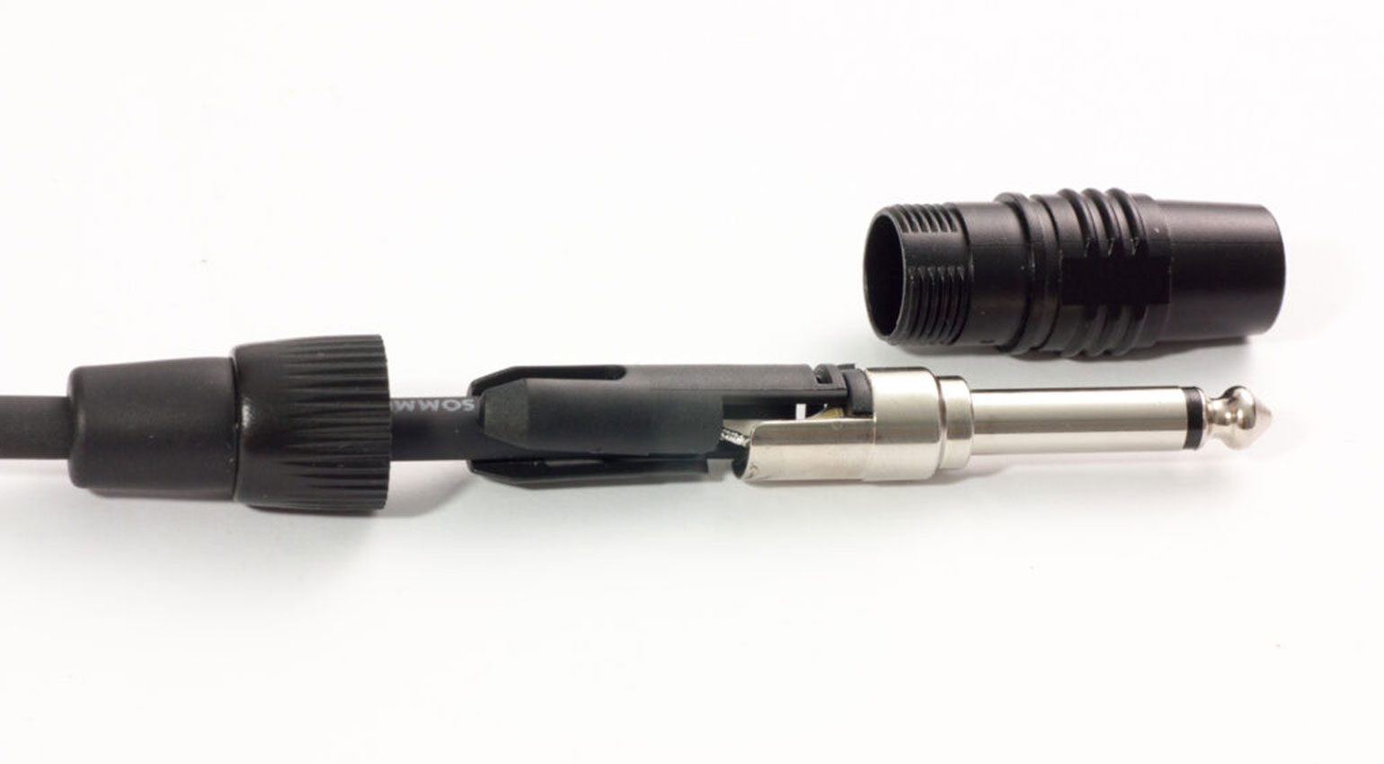
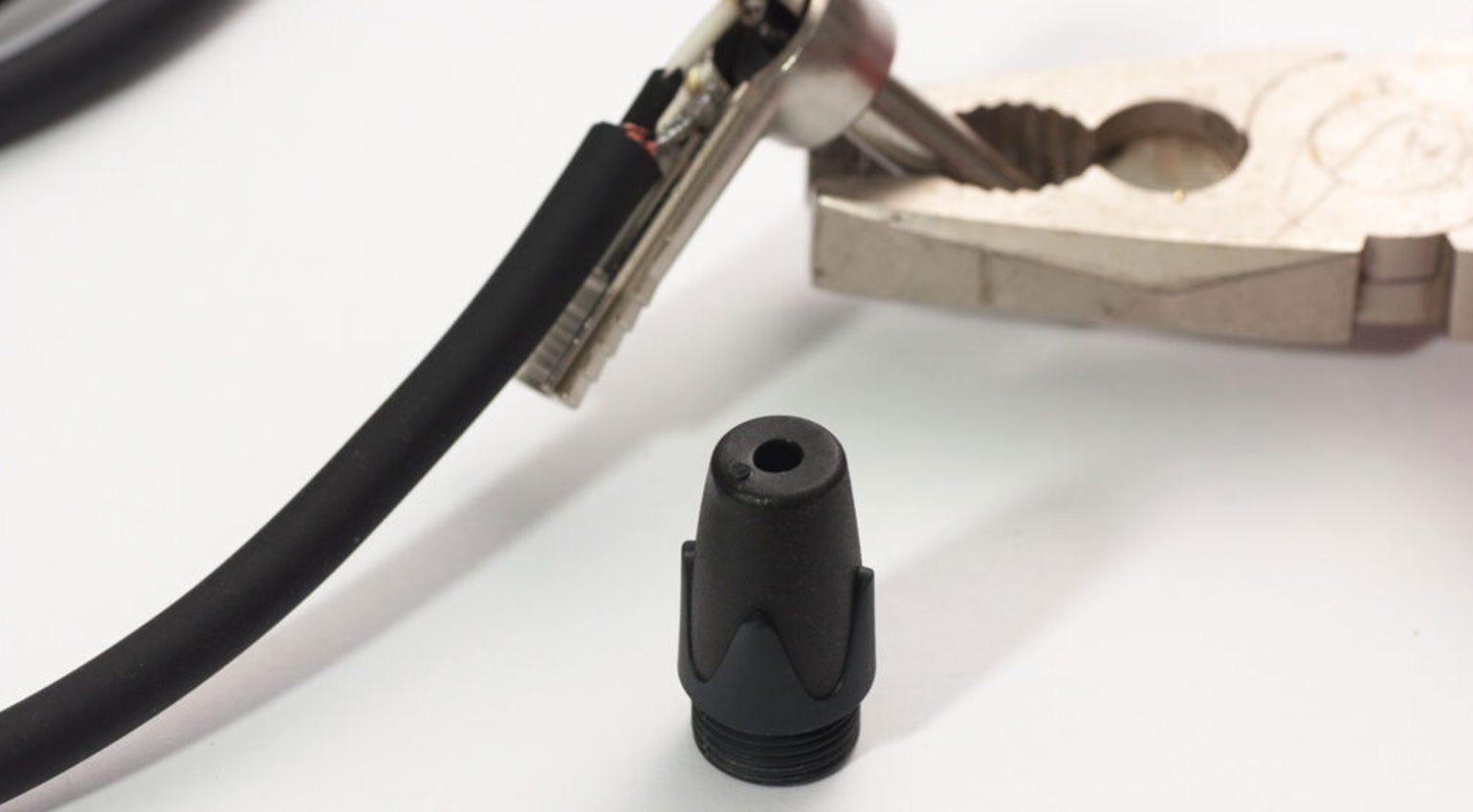
Every jack connector also has some form of strain relief system that protects the solder joints from mechanical stress. Some plugs have metal “jaws” that must be bent around the cable using pliers. More advanced designs use collets or chucks that are compressed by screwing the boot onto the plug, thereby holding the cable securely.
For guitar cables that see a lot of abuse, the collet design is by far the better choice. For less critical applications (e.g. patch cables), plugs with the simple jaw-type strain relief system can be more economical. One advantage of this design is that the connectors are usually slimmer than collet-type plugs, which makes them a good choice for cramped conditions.
How to Solder Instrument Cables: Step-by-Step Guide
Now that we’ve gone over the basics, it’s time to get to work. Here’s my step-by-step guide to soldering your own jack cables.
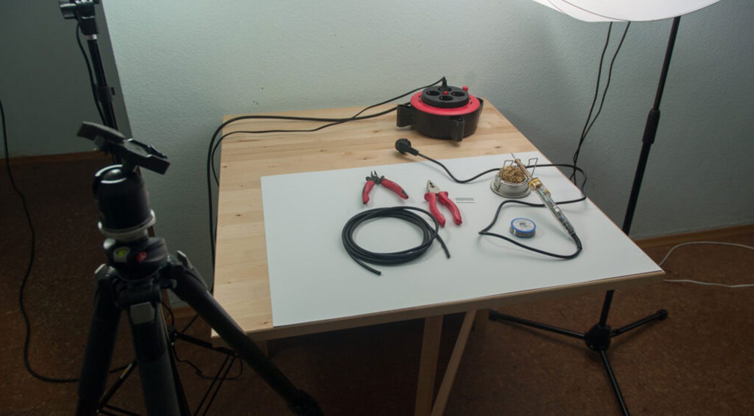
Step Zero: Prepare the Workplace
I’m not ashamed to admit that my soldering sessions usually begin by cleaning up. We need a clean workplace where all the tools we need are within easy reach. It is extremely important that the soldering iron can be moved freely from the stand to the component and back and that its cable cannot get caught or tangled. Be sure to practice the movement sequence with a cold soldering iron! If the cable gets caught, in the worst case it can pull the soldering iron out of your hand – and touching a hot iron is a seriously painful experience that must be avoided at all costs!
Step 1: Prepare the Material
The first step is to cut your bulk cable to the desired length. Sharp side cutters are the best tool for this job. Next, remove the connectors from their packaging, disassemble them, and lay all the parts out in front of you. Watch out for small parts – they love to roll off the table!
Step 2: Prepare Labels (Optional)
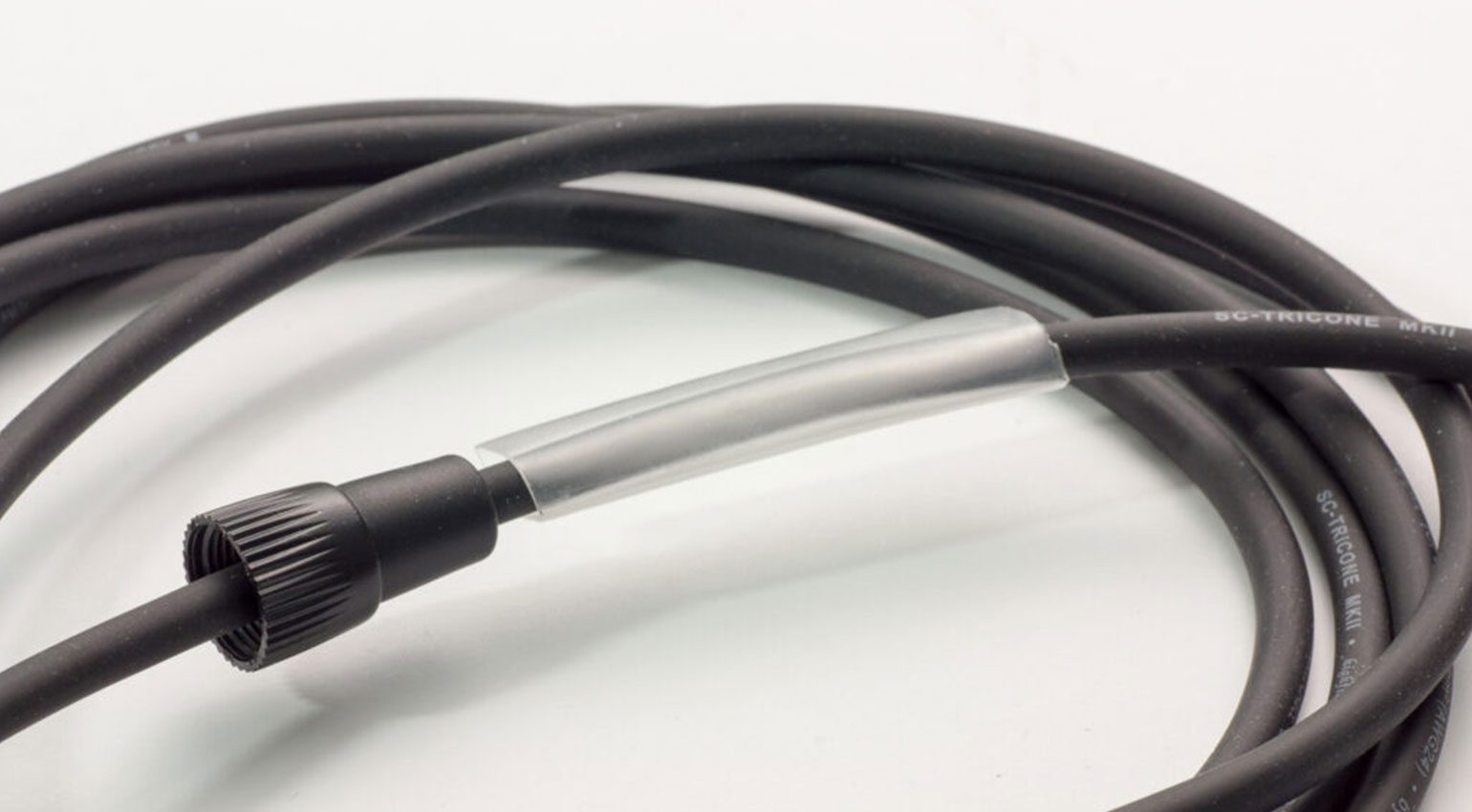
Now is also the time to think about marking and/or labeling your cables. Once the connectors are on, the unique chance to clearly mark your cables with your band name or your website is lost. A great way to permanently mark your cables is to use transparent heat shrink tubing, under which you can slide printed paper labels. A heat gun is the best method for shrinking.
Step 3: Slide the Boot, Insulating Sleeve and/or Heat Shrink Tubing Onto the Cable
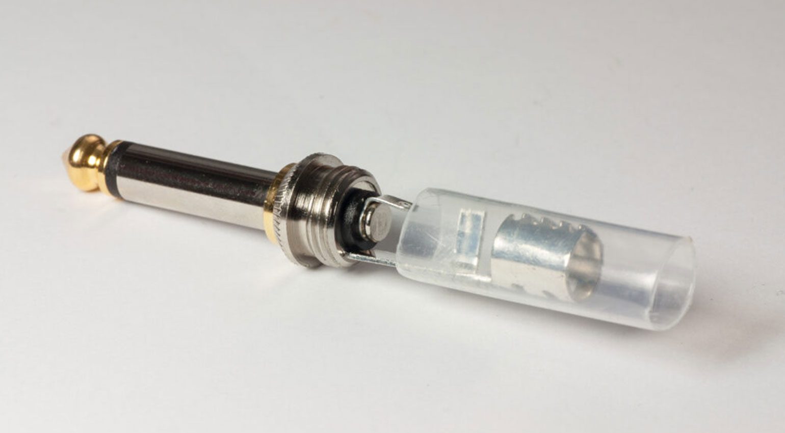
The boot or grommet is the part that is later screwed onto the plug from the back (cable side). I’ll write it in capital letters: DON’T FORGET TO SLIDE THE BOOT ON FIRST! Please print out this sentence and hang it on the wall at your workstation. But it’s probably a lost cause – sooner or later you will find yourself having to reheat your beautifully shiny solder joints because a crucial detail on the cable is missing: the boot! Don’t despair, it happens to the best of us.
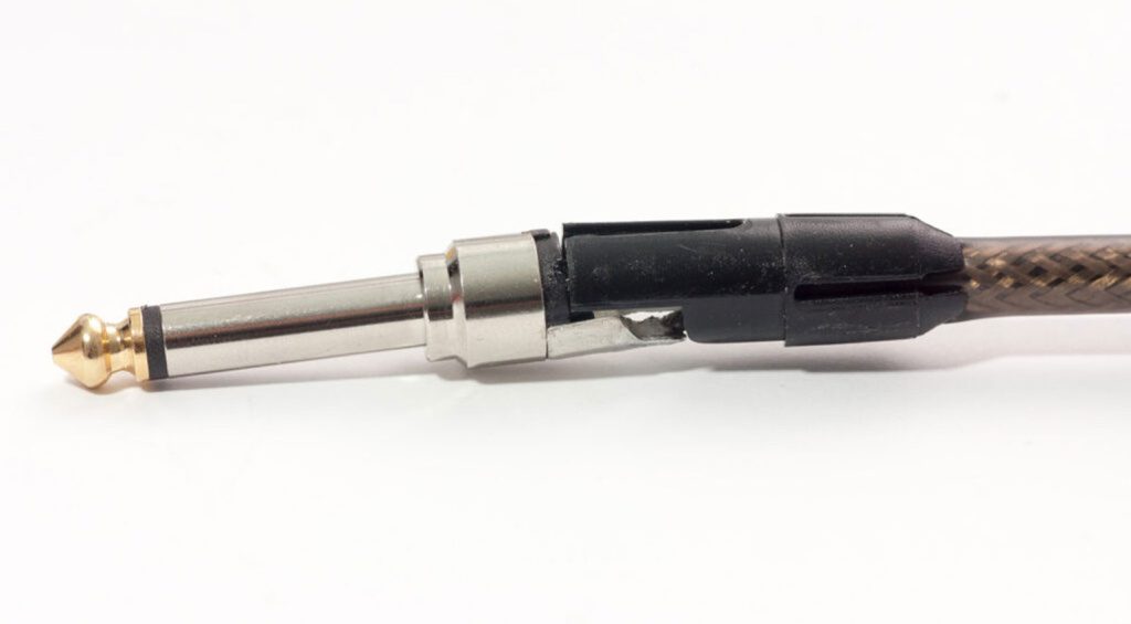
Plugs with jaw-type strain relief have a plastic sleeve (usually transparent) that covers the solder joints and insulates them from the housing. Like the boot, this must be slid onto the cable before soldering, so do it now!
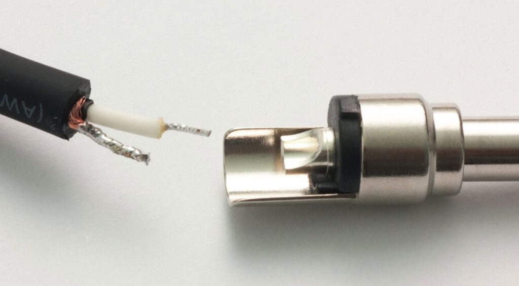
Step 4: Expose the Shield and Inner Conductor
Now we need to strip a piece of the outer jacket so we can get to the shield and inner conductor. How much of the jacket must be removed depends on the connector you are using. If in doubt, it is better to strip a little more, as you can always shorten the exposed shield and inner conductor later.
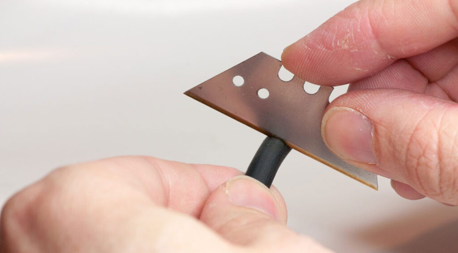
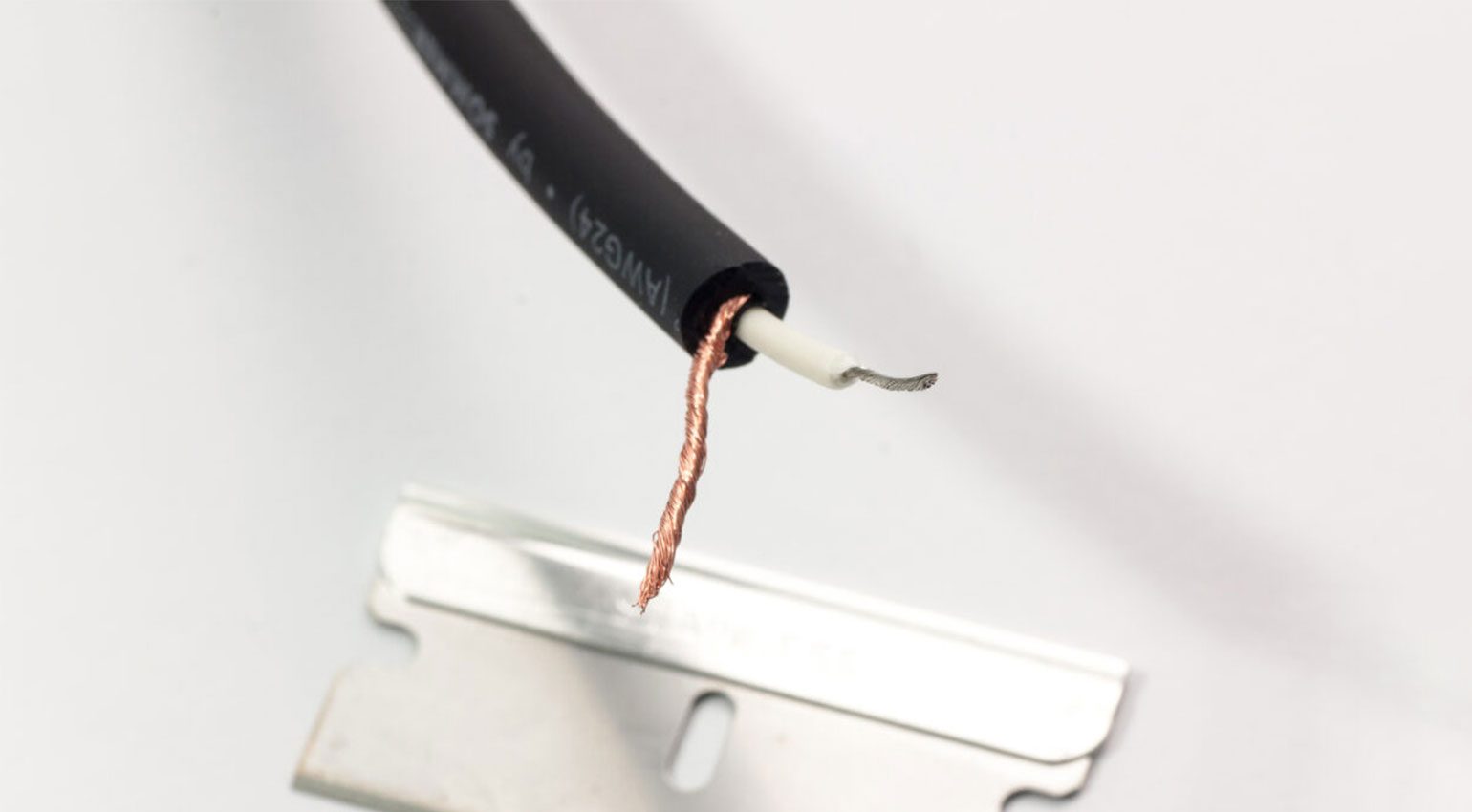
When removing the outer jacket of the cable, you have to be extremely careful not to damage the shielding or the insulation of the inner conductors. Everyone has their favorite method for stripping the jacket. Some use a sharp knife, I like to use a razor blade – preferably one that’s already a bit blunt. I believe this reduces the risk of damaging the wires.
First, make a cut around the entire circumference of the cable, but try not to cut all the way through to the bare copper just yet. Then bend the cable to open up the cut and carefully use your blade until you can see the copper. Work your way around the cable until you can strip the jacket off.
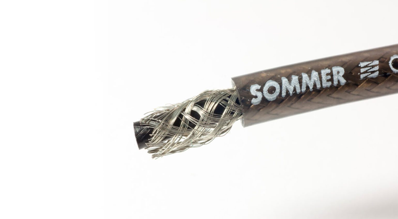
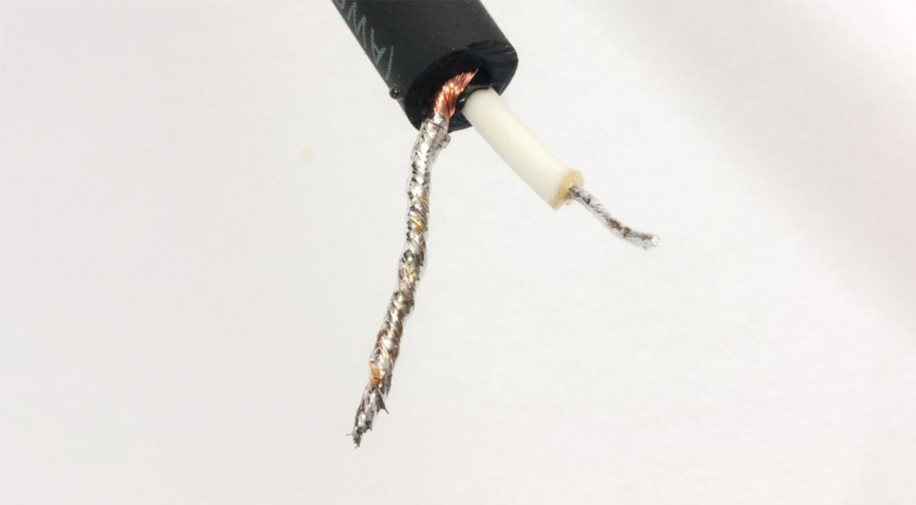
Step 5: Separate the Shield From the Center Conductor
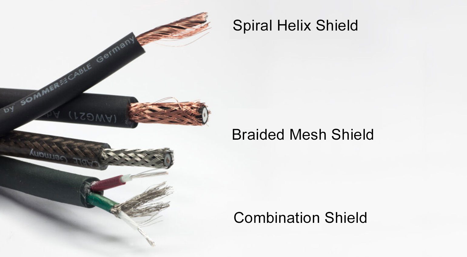
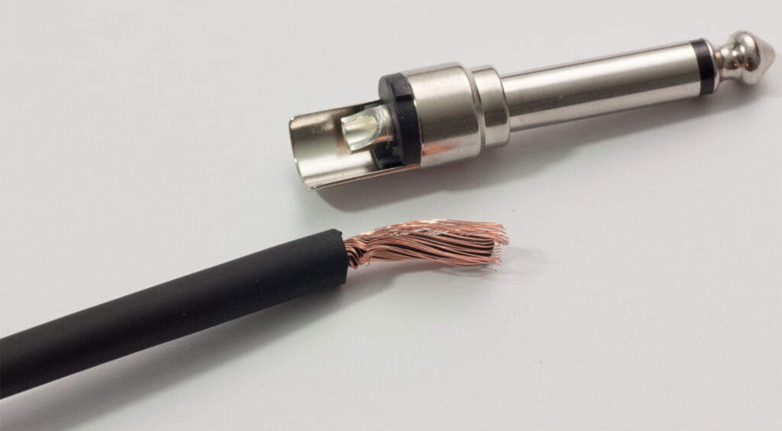
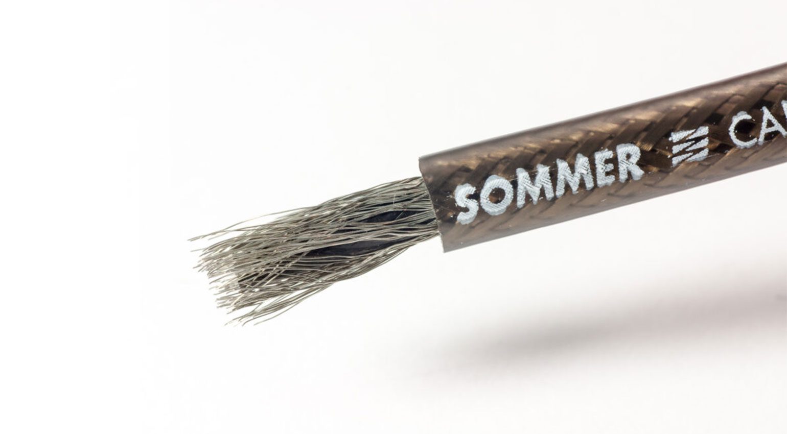
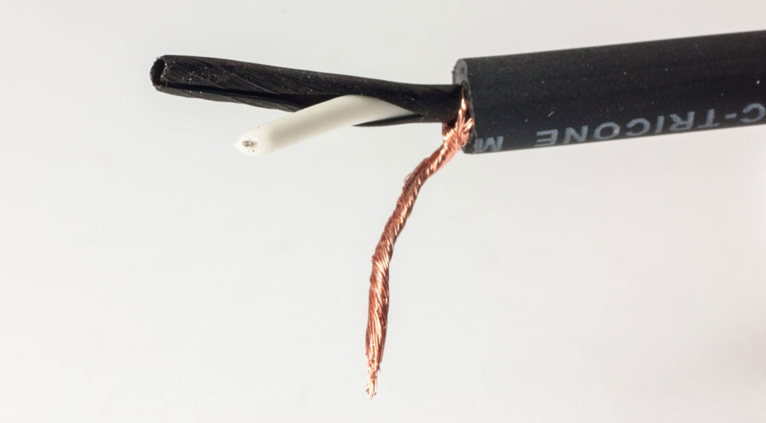
Once the jacket has been stripped, you have a clear view of the inner workings of the cable. The next step is to separate the shielding from the center conductor. Depending on the design of the shield, this can be quite tedious, but there is a simple trick: flick it with your finger! With a spiral shield, this only takes a couple of seconds, but even braided shields can be separated this way almost down to the jacket. A pointed object like a small screwdriver can take care of the rest.
Gather the strands on one side of the cable and twist them into a thick strand. Be careful not to lose any copper strands in the process!
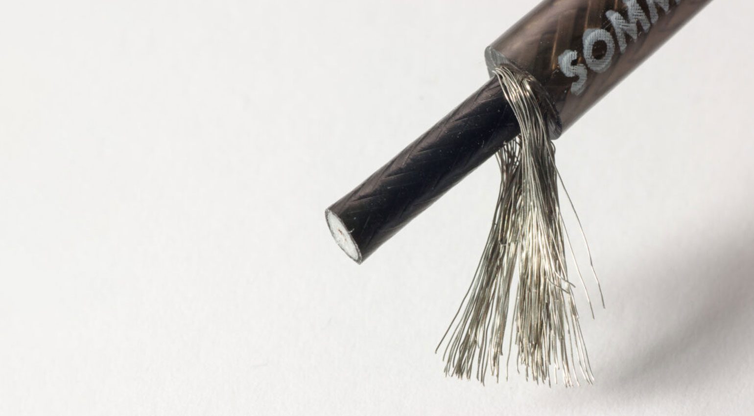
Step 6: Strip the Inner Conductor
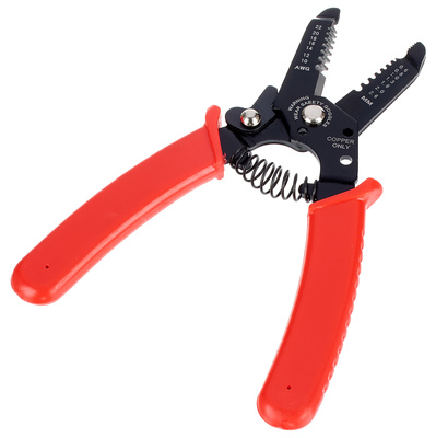
The next task is to remove the insulation from the inner conductor. You can do this again with the razor blade: Carefully cut the insulation all around with the blade. But you have to be much more careful not to damage the strands of the inner conductor – there are only a few! This is where it pays off if you’ve stripped a bit more of the outer jacket: if you make a mistake and accidentally damage the inner conductor, you can just cut off the damaged portion. Stripping wires is even easier and faster with special stripping pliers like these:

Now you have to twist the exposed strands again like you did with the shield.
Congratulations! The cable is now ready for soldering, so it’s time to bring the soldering iron to operating temperature.
How to Solder Instrument Cables: Safety Precautions
Before you pick up the hot soldering iron, allow me to say a few words about safety in the workplace. The first safety accessory you must have is a pair of safety goggles! Never solder without safety glasses! The hot solder can splatter if the soldering iron slips out of your hand or the workpiece falls down. Safety glasses are a must and you can get them at any hardware store for very little money.
Always ensure good ventilation in your workplace! The steam that develops during soldering is the burnt flux and you should not breathe in too much of it, because it is unhealthy. You don’t need to invest in a filtering system if you only solder occasionally, but do make sure there is enough fresh air. If the room doesn’t have a window, use a small fan to direct the soldering fumes away from you.
Once the soldering work is done, wash your hands thoroughly. Unlike professional manufacturers, many soldering amateurs still use leaded solder for the reasons I described in the beginning. Washing your hands prevents lead from entering your body. For longer soldering jobs, I use disposable gloves.
Last but not least, it goes without saying that you should keep your senses alert. The tip of the soldering iron reaches several hundred degrees – hot enough to cause serious burns and injuries! Don’t drink and solder!
Step 7: Tin the Shield and Inner Conductor
Tinning refers to the process of preparing the exposed copper strands for soldering by soaking them with solder. The textbook method is to first heat the copper wires with the soldering iron, and then touch the solder only to the strands until it melts and is drawn in. In practice, it helps to melt a bit of solder between the wire and the soldering iron at the beginning; this creates a thermal bridge that allows the solder to flow more easily.
Tinning is always done from the end of the wire towards the insulation and back again. If it is perfectly executed, the individual strands should still be visible, there should be no blobs of solder, and the insulation should stay intact. If you’ve never soldered before, it is best to practice this a few times on a bit of scrap wire.
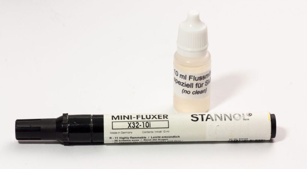
Tinning can sometimes be a bit tedious when the solder doesn’t really want to flow. The natural reaction is to leave the soldering iron in contact with the wire for longer, but this can cause the insulation to melt. But there’s a cool trick again, and it’s called a flux pen. These look like felt markers, but instead of ink, they contain additional flux that you can “paint” onto the stranded wire. This makes tinning a lot easier, the soldering iron doesn’t have to be brought all the way up to the insulation and the solder is still sucked quickly and deeply into the twisted strands.
Once you’re done tinning, the next step is to trim the tinned wires to the correct length for the connector you’re using.
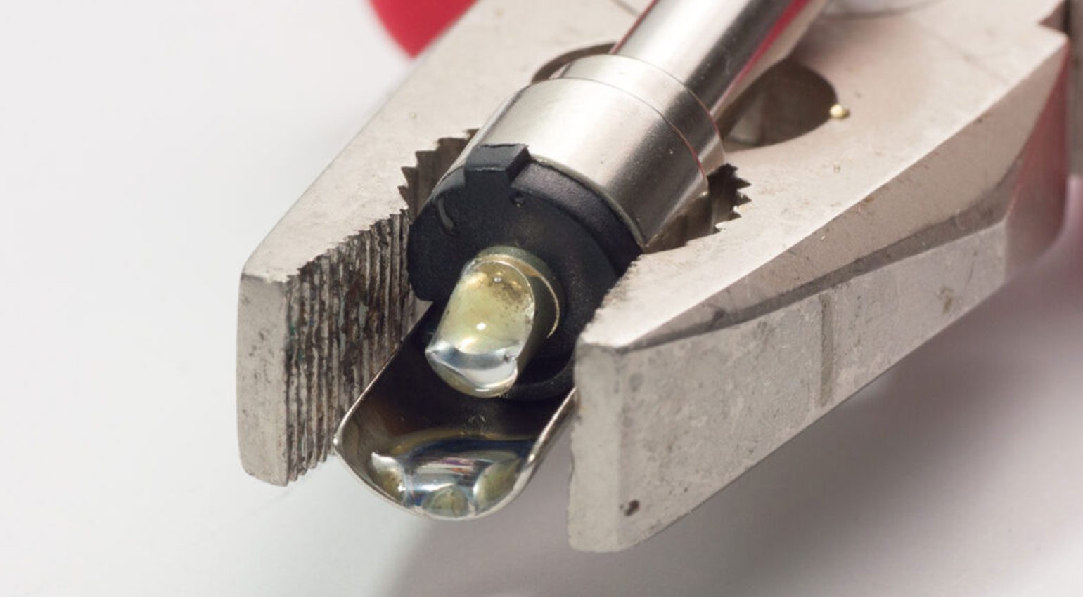
Step 8: Tin the Solder Terminals Of the Connector
Just like the wires, we now need to tin the solder terminals of the jack connectors for our instrument cable. The idea is to prepare the terminals by applying a sufficient amount of solder. And that could be less than you think! For soldering cups it is easy: Simply fill them with solder. For the screen, simply apply enough solder to the soldering tab to cover the screen later.
Normally, I’d use a vise to hold the connector in place during soldering. If you don’t have one, you can easily fashion a makeshift device using the rubber band mentioned at the beginning: Wrap it two or three times around the handle of some combination pliers and you have an excellent temporary holder for your connector.
Note: It may surprise you, but the holes in solder lugs do not have to be used. In fact, I advise against it! Why? I have yet to come across a malfunctioning cable where mechanical breakage of the solder joint itself was the culprit – provided, of course, that the joint was soldered correctly in the first place. From a mechanical point of view, it is not necessary to pull the strands through the holes in the soldering lugs, it can even be detrimental to the durability! The cable will also be much easier to repair if you simply solder the wire to the surface of the lug instead of pulling it through.
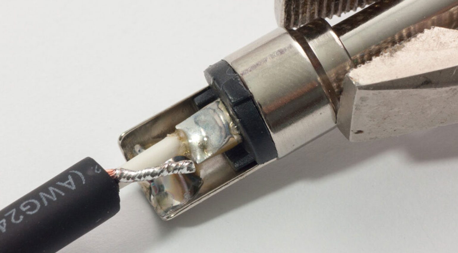
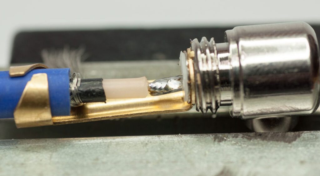
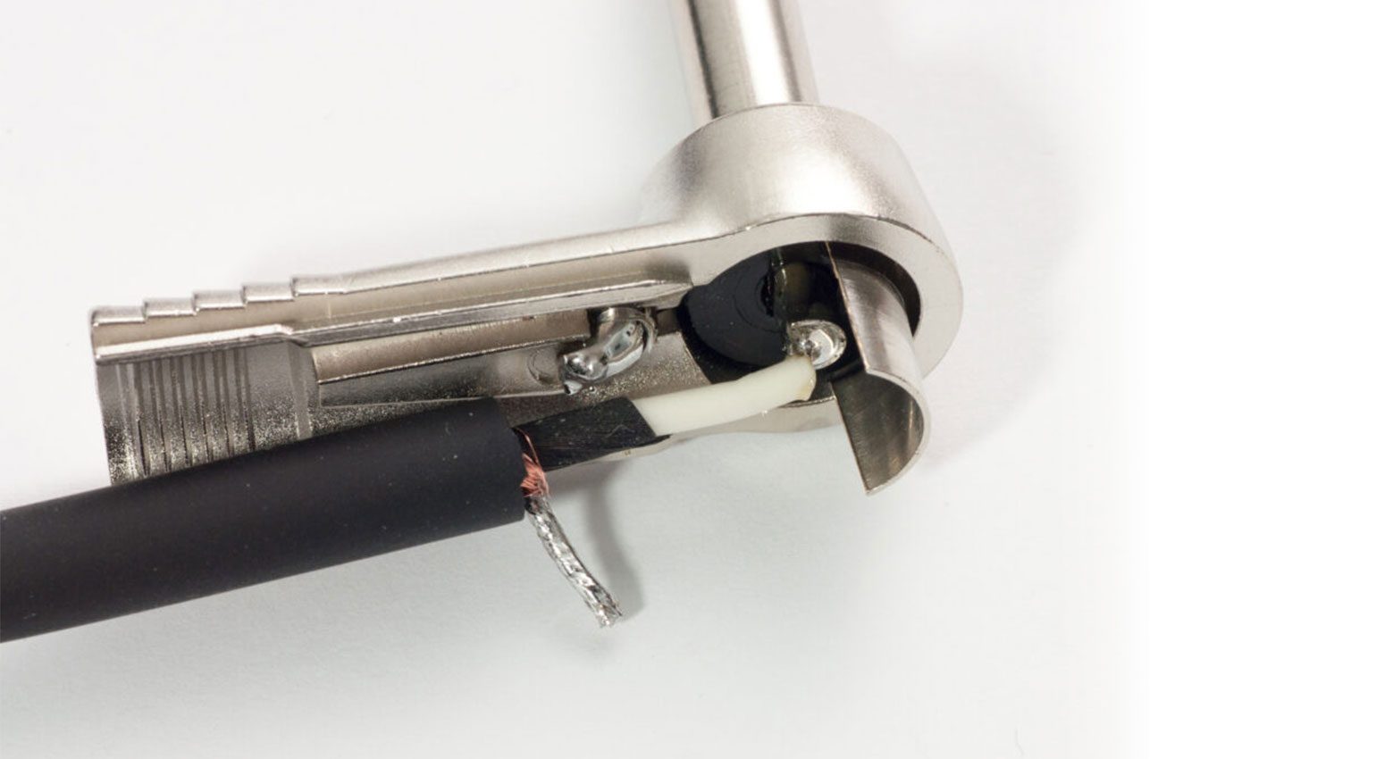
Step 9: Solder the Instrument Cable To the Connector
The next step is actually pretty easy: Heat the solder terminal until the previously applied solder liquefies again and press the tinned wire into the liquid solder. Leave the soldering iron in place for a couple of seconds, then remove it and watch the solder joint cool down. The whole process takes about four to five seconds. (You may have heard of a “one-second rule” for soldering, but we’ll leave that for PCB soldering – for wires, it’s perfectly fine if it takes a bit longer.) If it takes longer than five seconds, your soldering iron isn’t hot enough!
Whether you solder the shield or the signal wire first depends a bit on the type of connector and the accessibility of the solder terminals. This can be a rather tight affair. That’s another reason why it’s best not to use too much solder, as this minimizes the risk of creating a short circuit.
The process is similar for connectors with solder lugs, although there’s no little “cup” to fill. Simply apply about a lentil-sized drop of solder to the lug.
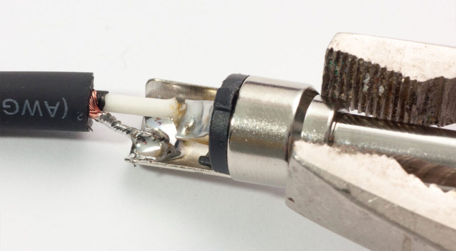
Step 10: Assemble the Connector
If you want to be neat, you can now clean up the solder joints with alcohol or acetone to remove flux residues. And then it’s time to inspect the solder joints visually and mechanically. Check your work for protruding strands of wire. The individual contacts must not be short-circuited via solder bridges. The insulation should end just before the solder joint and it should not be charred. Take a close look at the joints, preferably using a magnifying glass if you have one. A proper solder joint is shiny (this only applies to leaded solder!). Then pull on the cable – if your solder joints are good, they won’t take it badly.
When you’re satisfied with your work, you can assemble the housing of the connector. And this is when you’ll notice that you’ve forgotten something: the boot …
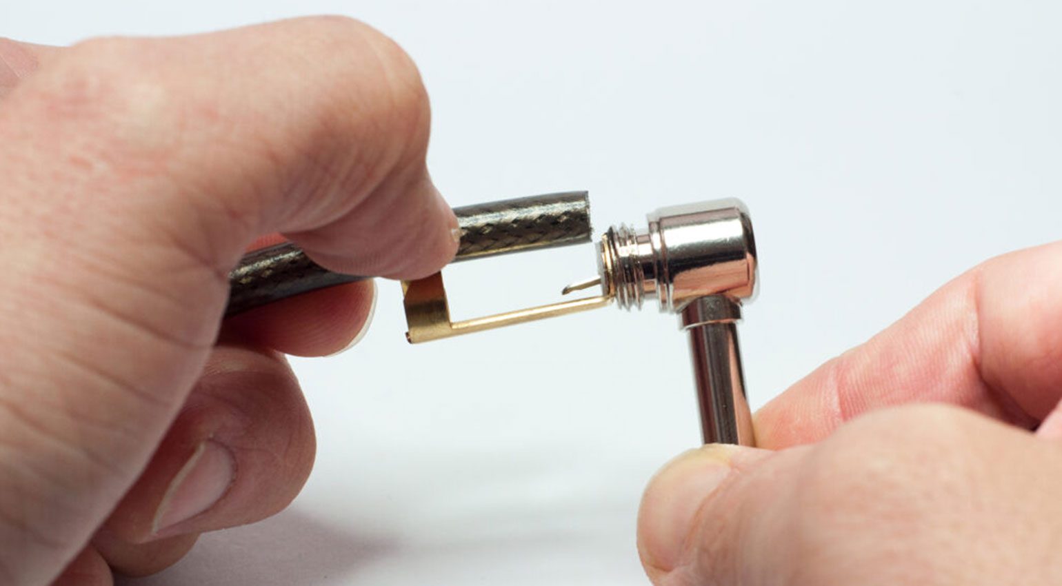
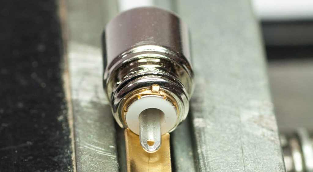
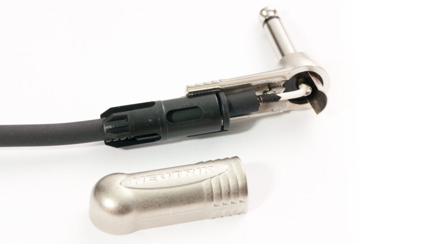
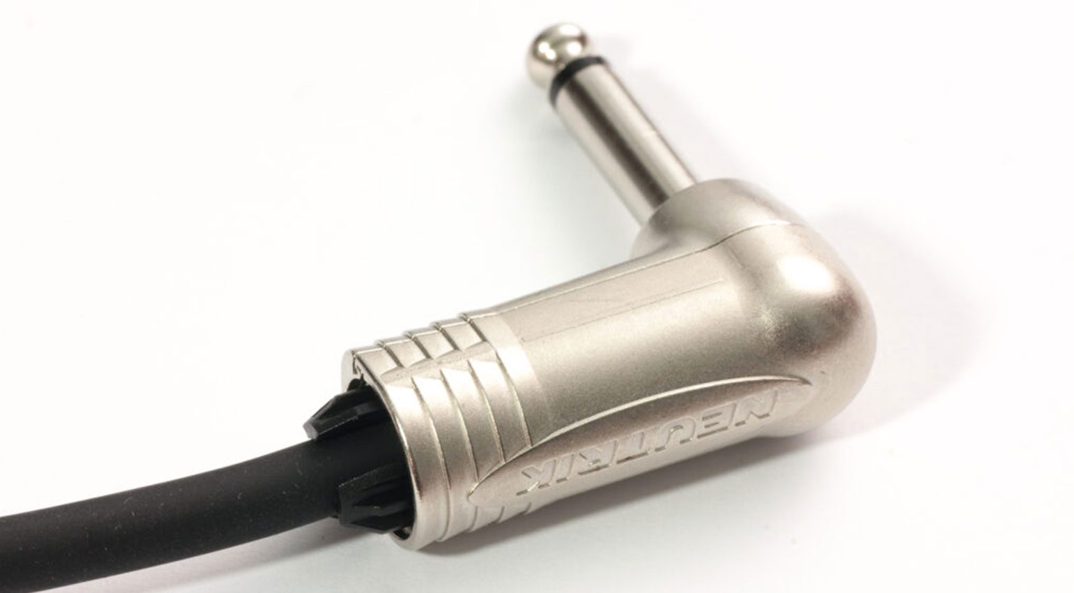
How to Solder Instrument Cables: Angled Plugs
For the other end of the cable, we’re using an angled jack connector from Neutrik. Steps 3 through 5 are the same: slide the boot onto the cable, strip the jacket, expose and twist the shield, strip the inner conductor, and tin the wires. However, the solder terminals of this connector are arranged differently and look somewhat different.
Now you have to trim the tinned wires to the right lengths again. Then you can solder the inner conductor and shield to the terminals. Heat the terminal, push the tinned wire into the liquid solder, remove the soldering iron, and wait with a steady hand until the solder has hardened. It really sounds more difficult than it actually is!
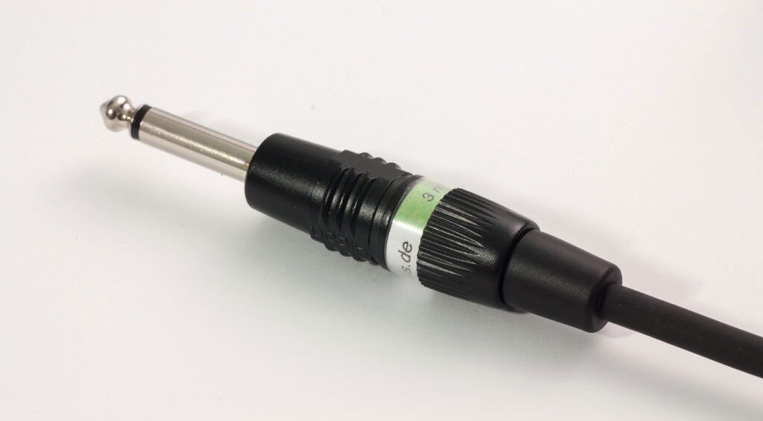
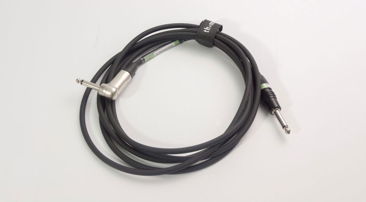
If you’ve made it to this point, you should now have a working jack cable in your hands! If you’ve added transparent heat shrink tubing for labeling, you can now slide the label underneath it and heat it until it shrinks. And now, there’s only one step left: testing the cable.
Step 11: Testing the Instrument Cable After Soldering
In the workshop, I’d now reach for my multimeter to test the cable. But that doesn’t replace a test under real-world conditions – after all, we want the cable to work between the guitar and amp, not just under lab conditions. It’s actually quite simple: If what comes out of the amp sounds like the connected instrument, you can pat yourself on the back: your cable has passed the test. If, on the other hand, there is a crackling noise when you move the cable or jiggle the connectors, this can be an indication of a cold solder joint. The only thing that helps in this case is to take the connector apart again and re-solder the joint in question.
Congratulations on your first cable! I hope I was able to show you that soldering your own instrument cables isn’t difficult at all!
More DIY Tips For Guitar
- Make your cheap Squier play like an American Fender: Three easy upgrades
- Make your Cheap Squier sound like an American Fender: Soldering Basics
- Make your Cheap Squier sound like an American Fender: Upgrade your Potentiometers!
- How to Set Up your Guitar: Beginner’s Guide to Guitar Setup
This article was originally published in German on bonedo.de.
*Note: This post contains affiliate links and/or widgets. When you buy a product via our affiliate partner, we receive a small commission that helps support what we do. Don’t worry, you pay the same price. Thanks for your support!


This might also interest you


8 responses to “How To Solder Instrument Cables: 11 Steps To Make Your Own Jack Cable!”
This is such a great article!! Thank you for taking the time to do it thoroughly with great photos. 🙂
Great article with lots of useful information. I’ve failed at making midi cables and would love an article on that as well.
oh. even as a wannabe skilled solderer, this is a brilliant article, thanks a lot for the precious details – much appreciated.
Really brilliant article.
More like this please, and less of the “top 5” list type of articles.
Thorough and helpful guide!
These cables are inherently susceptible to damage, especially when used in various locations. No matter how careful you are, wear and tear are inevitable. Learning to solder and repair them is a valuable skill, and this guide is a fantastic resource thanks.
Thanks a million! this information was helpful.
you can get by with a regular pair of pliers in a bind but it’ll be much easier with a wire stripper (and for the next level comfort: a specialized tool to remove the sheath of cables). The wire stripper will also have a cutting section so you can have only one tool to carry.
You are currently viewing a placeholder content from Facebook. To access the actual content, click the button below. Please note that doing so will share data with third-party providers.
More InformationYou are currently viewing a placeholder content from Instagram. To access the actual content, click the button below. Please note that doing so will share data with third-party providers.
More InformationYou are currently viewing a placeholder content from X. To access the actual content, click the button below. Please note that doing so will share data with third-party providers.
More Information